
Introduction
P&ID, short for Piping and Instrumentation Diagram, is a crucial visual representation in the field of engineering. It serves as a blueprint that outlines the interconnection of piping, equipment, instrumentation, and controls within a process system. P&IDs are indispensable tools in industries such as chemical, petrochemical, manufacturing, and energy. This comprehensive guide unveils the intricacies of P&IDs, their components, significance, and the role they play in process engineering.
Don’t miss the Complete Course on Piping Engineering: Check Now
By EPCLand.com
Table of Contents
The Basics of P&ID
Understanding the Essence
A Piping and Instrumentation Diagram (P&ID) is a schematic representation that illustrates the relationships between various equipment, piping, instrumentation, and controls in a process system. It provides a clear visual overview of the process flow and the components involved.
Components of a P&ID
A P&ID comprises several essential components:
Process Equipment
Process equipment such as pumps, compressors, heat exchangers, and reactors are represented with standardized symbols. These symbols denote the type, size, and function of each piece of equipment.
Piping
Piping lines are drawn to depict the connections between different equipment and components. Various line types indicate the nature of the fluid being transported (liquid, gas, steam, etc.), while arrows indicate the flow direction.
Instrumentation and Control Devices
Instruments like sensors, transmitters, control valves, and flow meters are represented on the diagram. Each instrument is labeled with a tag that corresponds to a database containing detailed information about its properties and purpose.
Annotations and Notes
Annotations and notes provide additional information about the process, equipment, or specific components. These help engineers and operators better understand the system’s operation and maintenance requirements.
P&ID Symbols and Standards
P&ID symbols follow standardized conventions set by organizations such as the International Organization for Standardization (ISO) and the American National Standards Institute (ANSI). These symbols ensure consistency and universal understanding across industries and regions.
Evolution of Piping and Instrumentation Diagrams
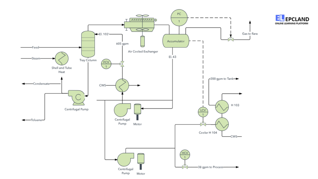
In the chronicles of engineering documentation, the Piping and Instrumentation Diagram (P&ID) emerges as a pivotal artifact. Typically crafted during the planning phase of a process flow, this diagram serves as a navigational guide for implementers during plant setup. However, the annals of process depiction reveal an antecedent chart known as the Process Flow Diagram or PFD.
A Process Flow Diagram unveils the architectural blueprint of the conceptual workflow. It outlines the orchestration of fully functional equipment post-installation, illuminating the machinery’s intended operation. Unlike P&IDs, the PFD refrains from inundating the scene with granular specifics like figures, numbers, or meticulous measurements.
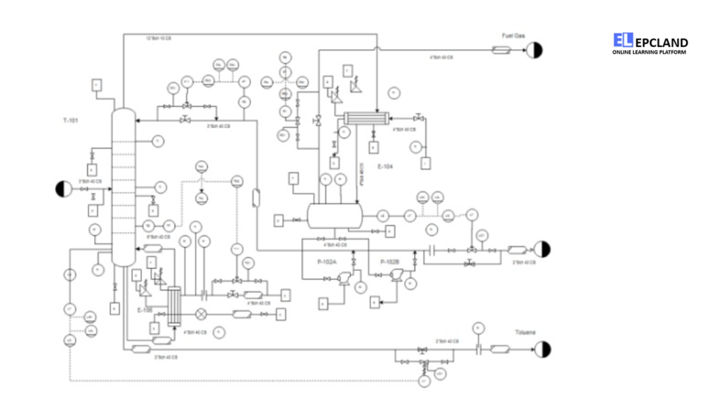
Following the creation of a PFD, this blueprint assumes the mantle of reference documentation for the subsequent construction of a P&ID. Within the P&ID’s realm lies the meticulous portrayal of workflow intricacies: the piping framework, the mechanical components, and other pivotal units. Yet, it is crucial to grasp that the essence of a P&ID lies in spotlighting the vital pipes and machinery, thus avoiding excessive intricacies. In instances where a specific segment of the Piping and Instrumentation Diagram warrants deeper elucidation, the prudent course is to forge a distinct diagram dedicated solely to that segment.
Don’t miss the Complete Course on Piping Engineering: Check Now
By EPCLand.com
The Significance of P&ID in Engineering
Ensuring Clarity and Consistency
P&IDs are vital tools for engineers, operators, and maintenance personnel. They offer a clear, standardized representation of complex systems, reducing misunderstandings and errors in communication.
Design and Engineering
During the design phase, P&IDs aid in making critical decisions regarding equipment placement, pipe routing, and process flow. Engineers can identify potential issues early on and make informed adjustments.
Operational Understanding
P&IDs serve as a valuable reference for operators to understand how a system operates. They provide insights into the location of valves, instruments, and controls, helping operators manage processes efficiently.
Maintenance and Troubleshooting
When maintenance or troubleshooting is required, P&IDs offer a roadmap. Operators can quickly locate components, identify potential problems, and carry out corrective actions.
Understanding the Role and Significance of P&IDs
Piping and Instrumentation Diagrams (P&IDs) serve as fundamental tools for both maintaining and adapting the processes they visually represent. During the design phase, these diagrams lay the groundwork not only for system control schemes but also for critical assessments like Hazard and Operability Study (HAZOP).
In the context of processing facilities, P&IDs stand as visual depictions that encapsulate:
- Essential piping and instrumentation details
- Comprehensive control and shutdown strategies
- Vital safety and regulatory prerequisites
- Fundamental startup and operational insights
Applying P&IDs: When and Who
P&IDs manifest as schematic illustrations, delineating the intricate connections between piping, instrumentation, and system equipment components within the sphere of instrumentation, control, or automation. Typically crafted by engineers entrusted with designing manufacturing processes for physical plants, these diagrams hold particular relevance in such contexts.
These manufacturing facilities often involve intricate chemical or mechanical sequences, mapped meticulously using P&IDs for constructing and ensuring plant safety. These diagrams become crucial reference points for Process Safety Information (PSI) within the domain of Process Safety Management (PSM). Should any anomalies arise, scrutinizing the P&ID is often a prudent starting point. Their value extends further, offering an indispensable repository for managing process changes safely and efficiently through Management of Change (MOC) protocols.
P&IDs cater to a diverse audience, including field technicians, engineers, operators, and even those in training or contract roles, enhancing their understanding of process intricacies and instrument interconnections.
Exploring the Essence of P&IDs
While P&IDs are instrumental in illustrating process interconnectivity, they might not explicitly contain specifications; such information often resides in separate documentation. However, the utility of P&IDs is profound, encompassing various functions such as:
- Evaluating construction methodologies
- Serving as a foundation for control programming
- Formulating guidelines and operational standards
- Creating documents elucidating process functionality
- Establishing a shared vocabulary for plant operations discourse
- Crafting safety and control philosophies
- Conceiving conceptual layouts for chemical or manufacturing plants
- Yielding insights for cost estimates, equipment design, and pipe layout recommendations
In essence, P&IDs stand as indispensable assets in the realm of process engineering, imparting a visual understanding of complex systems and fostering effective communication across stakeholders. As dynamic tools, they empower various aspects of industrial operations, from design and implementation to maintenance and safety management.
Unpacking P&ID Support Documents
Given that P&IDs serve as schematic overviews, they necessitate supplementary documentation for detailed understanding and specification clarification. Some essential support documents include:
- Process Flow Drawings (PFDs): P&IDs are derived from PFDs, which depict process steps in sequence. PFDs encapsulate inputs, outputs, decisions, involved parties, timeframes, and process measurements.
- Piping Material Specifications (PMS): This document elucidates construction materials, gaskets, bolts, and fittings.
- Equipment and Instrumentation Specifications (EIS): The EIS offers extensive standards and details not encompassed by P&IDs. It encompasses aspects like construction materials, design basis, testing procedures, and more.
- Functional Requirement Specification (FRS): The FRS outlines how a plant or system functions. It encompasses functional descriptions, communication protocols, and scope definitions.
In essence, while P&IDs provide a valuable visual understanding of intricate processes, they necessitate a supporting framework of documentation to encapsulate the intricacies and ensure accurate design, operation, and maintenance.
Don’t miss the Complete Course on Piping Engineering: Check Now
By EPCLand.com
Creating and Interpreting P&IDs
Creating P&IDs
- Gather Information: Collect data on equipment, instruments, and process requirements.
- Choose Software: Utilize specialized software for P&ID creation, ensuring accuracy and ease of modification.
- Drag-and-Drop Symbols: Place symbols for equipment and instruments onto the canvas.
- Connect Components: Use appropriate line types to connect components and indicate flow direction.
- Label and Annotate: Add tags, labels, and annotations to provide context and details.
- Review and Validate: Thoroughly review the P&ID for accuracy and adherence to standards.
Interpreting P&IDs
- Understand Symbols: Familiarize yourself with standard P&ID symbols and their meanings.
- Follow the Flow: Trace the flow of fluids and materials through the system using arrows and line types.
- Identify Components: Locate equipment, instruments, and controls using their corresponding symbols and tags.
- Read Annotations: Pay attention to annotations and notes for additional information on components and processes.
- Cross-Referencing: Use equipment tags to cross-reference the P&ID with databases containing detailed specifications.
Essential Inclusions in a P&ID
What constitutes a well-structured Piping and Instrumentation Diagram (P&ID)? While there isn’t a rigid blueprint for their creation, the Process Industry Practice (PIP), a collective effort involving process industry stakeholders and engineering construction contractors, has proposed standards. Specifically, the document PIC001: Piping and Instrumentation Diagram Documentation Criteria outlines the core components that a comprehensive P&ID should encompass:
- Mechanical Equipment: Clearly labeled with names and unique identifiers.
- Valves: All valves identified with appropriate tags.
- Process Piping: Displayed with sizes and distinctive identification.
- Miscellaneous Elements: Vent and drain lines, specialized fittings, sampling lines, reducers, increasers, and swagers.
- Start-up and Flush Lines: Highlighted for permanent reference.
- Flow Directions: Indicating the flow path of materials.
- Interconnections: Referencing connections between various components.
- Control Inputs and Outputs: Detailing the control mechanism.
- Interlock Notations: Indicating interlocking mechanisms.
- Seismic Category: Categorization based on seismic considerations.
- Class Interface Points: Marking interfaces for class changes.
- Quality Level Indicators: Displaying the quality level of components.
- Annunciation Inputs: Inputs for notifications and alerts.
- Computer Control System Input: Interfaces with computerized control systems.
- Vendor and Contractor Interfaces: Identification of third-party components.
- External Components: Delineation of subsystems delivered by external entities.
- Equipment Sequence: Intended physical arrangement of equipment.
- Equipment Rating or Capacity: Displaying operational capacities.
Exclusions from P&IDs: Focus on Clarity
While comprehensiveness is essential, overloading P&IDs with intricate specifics can lead to clutter. For a clear and coherent representation, it’s prudent to avoid including the following details within P&IDs:
- Instrument Root Valves
- Control Relays
- Manual Switches
- Primary Instrument Tubing and Valves
- Pressure, Temperature, and Flow Data
- Standard Fittings (Elbows, Tees, etc.)
- Extensive Explanatory Notes
In essence, P&IDs serve as streamlined visual tools, capturing essential details without overwhelming the viewer. The delineation of what to include and what to omit ensures that P&IDs effectively communicate critical information while maintaining their clarity and purpose.
P&ID Symbols and Notations: Standardizing Communication
Piping and Instrumentation Diagrams (P&IDs) encapsulate a standardized vocabulary of symbols and notations, serving as the linchpin for comprehending these visual representations. When it comes to instrumentation symbols, uniformity is established through adherence to the ANSI/ISA S5.1-1984 (R 1992) standards. This alignment with the Instrumentation, Systems, and Automation Society (ISA) S5.1 Instrumentation Symbols and Identification standard guarantees a coherent and system-independent avenue for conveying instrumentation, control, and automation intent to ensure universal understanding.
ISA S5.1 delineates four distinct graphical elements: discrete instruments, shared control/display mechanisms, computer functions, and programmable logic controllers (PLCs). These elements are categorized into three location groups—primary location, auxiliary location, and field mounted.
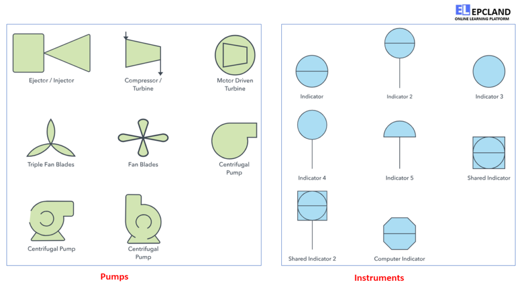
Circular elements signify discrete instruments. Shared control/display features manifest as circles enclosed within squares. Hexagons denote computer functions, while programmable logic controller (PLC) functions are depicted as triangles within squares.
A solitary horizontal bar across any graphical element designates primary location classification. A dual line signifies an auxiliary location, and the absence of lines situates the device or function within the field. Devices situated behind inaccessible panel-boards are indicated by a dashed horizontal line.
The integration of letter and number combinations within each graphical element is pivotal. Letter combinations conform to the definitions outlined by the ISA standard, whereas numbers are user-assigned. Numbering schemes vary—some opt for sequential numbering, while others tie instrument numbers to process line numbers. Diverse and occasionally unconventional numbering systems may be adopted.
The initial letter within a combination defines the measured or initiating variables. Examples encompass Analysis (A), Flow (F), and Temperature (T), while succeeding letters elucidate readout, passive, or output functions such as Indicator (I), Record (R), and Transmit (T).
Here are several instances of P&ID symbols. For a comprehensive overview of all P&ID symbols, Lucidchart offers an inclusive resource if further reference is required.
Diverse Symbol Categories on P&IDs
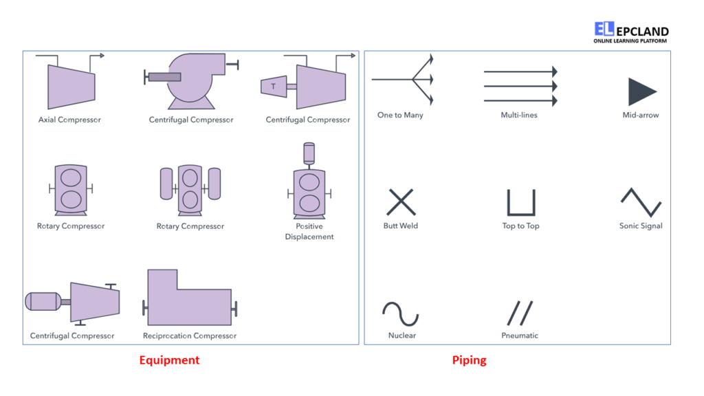
Equipment: This category encompasses miscellaneous P&ID units that elude conventional classification. Comprising hardware like compressors, motors, and turbines, it also includes mechanical devices like conveyors and vacuums.
Piping: Serving as conduits for fluid substances, pipes transport liquids or gases. Piping units encompass diverse materials like metal and plastic, with the group embracing single and multi-line pipes, as well as separators.
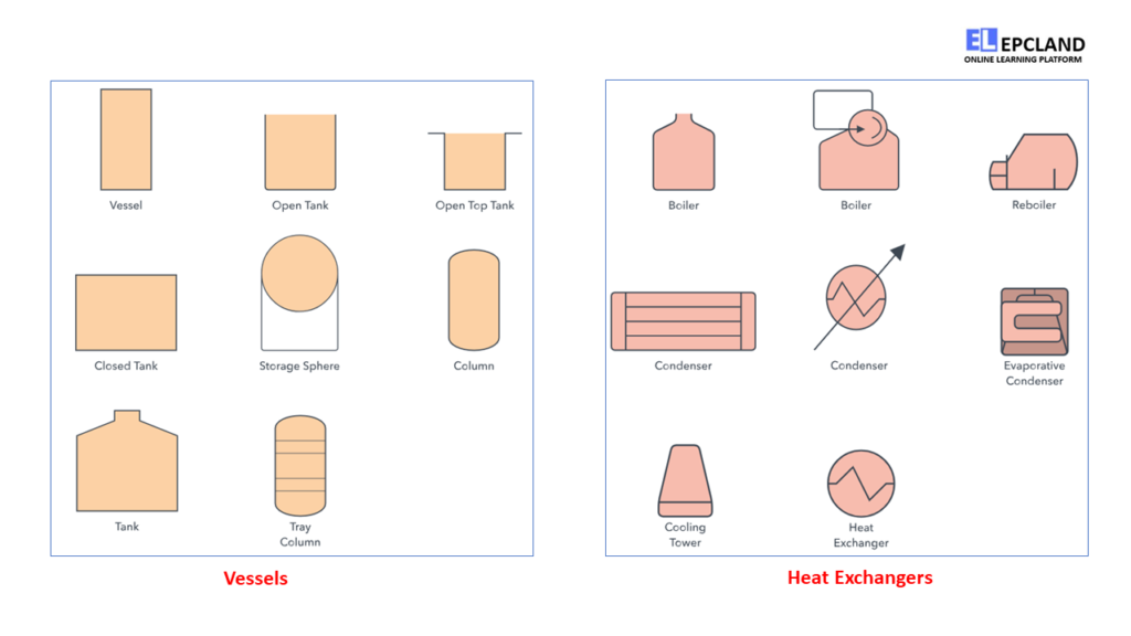
Vessels: Vessels are containers designed for fluid storage, which might induce alterations in fluid characteristics. Tanks, columns, bags, and cylinders are among the vessel category constituents.
Heat Exchangers: These devices efficiently transfer heat across different mediums. Boilers, condensers, and similar mechanisms are encapsulated within the heat exchanger group.
Pumps: Pumps employ pressure or suction to manipulate fluid movement. This segment accommodates both pumps and fans, pivotal in fluid dynamics.
Instruments: Instruments quantify and occasionally regulate various quantities such as temperature and pressure. This category comprises indicators, transmitters, controllers, and recording mechanisms.
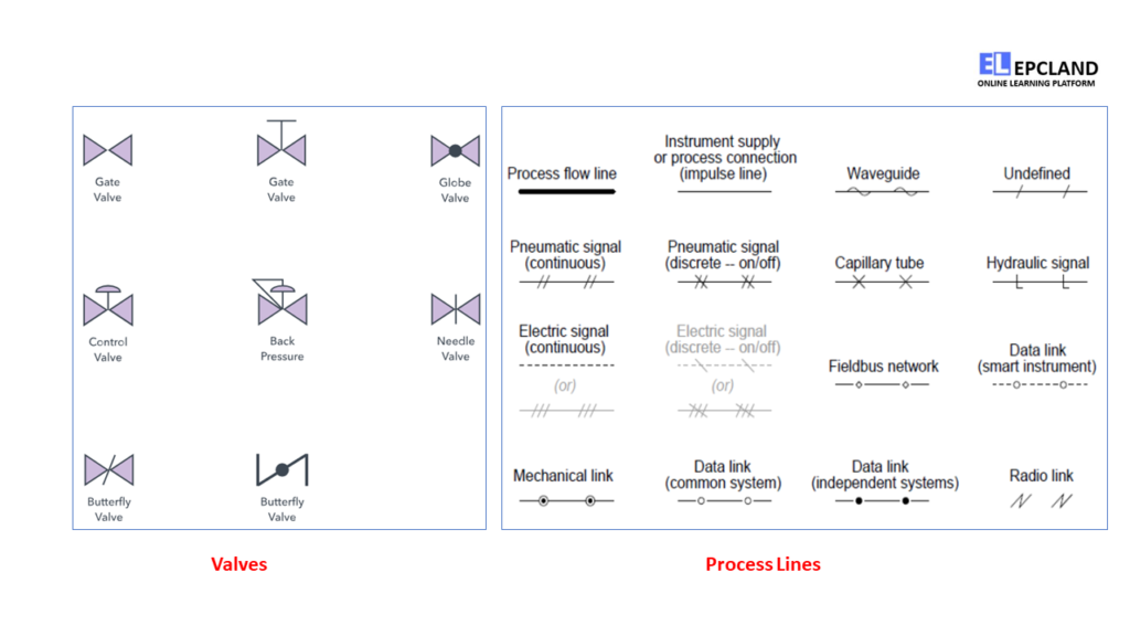
Valves: Valves modulate fluid flow by opening, closing, or partially obstructing passageways. The valve category incorporates an array of valve types, including rotameters and orifices.
In essence, P&ID symbols and notations forge a standardized language, fostering effective communication across the spectrum of engineering, design, and operation. These symbols enable seamless understanding and interpretation, facilitating the construction and management of complex systems.
Don’t miss the Complete Course on Piping Engineering: Check Now
By EPCLand.com
Applications of P&ID Drawings in Various Scenarios
Advancing Process System Development: Piping and Instrumentation Diagrams (P&IDs) emerge as schematic illustrations offering a primary visual representation of process control systems. Within these diagrams, the conceptual design process takes tangible shape, portraying essential details that bridge the gap between the abstract and the tangible. By revealing the interconnections among piping, equipment, vessels, and process components, P&IDs become instrumental in the developmental journey, steering towards comprehensive and detailed engineering.
Elevating System Safety Design: As the development process unfurls, a prime concern becomes the integration of safety features. Unaddressed hidden hazards can cast shadows over the seamless evolution of a process plant. Here, P&ID drawings emerge as sentinels, unraveling potential risks before they morph into operational impediments. These diagrams illuminate the intricate dance of processes and the plant’s environmental context, fortifying the foundation of safety by preemptively averting hazards.
Navigating Management of Change: P&ID diagrams stand as beacons in times of unforeseen challenges during the development journey. These diagrams serve as integral engineering documents, intricately mapping out diverse processes and the materials orchestrating the plant’s existence. During moments of necessary alterations, P&IDs provide a rudder for managing change, ensuring that discrepancies are rectified. They offer a steady framework within which alterations can harmoniously align with the existing design.
Guiding Plant Maintenance and Evolution: The inexorable march of time inevitably leaves its mark on the materials and process components constituting a plant. Wear and tear inevitably set in, prompting the need for meticulous maintenance and even occasional modifications. P&IDs assume a pivotal role, serving as ever-watchful companions throughout the trajectory of maintenance and evolution. They facilitate informed decision-making by meticulously guiding maintenance procedures and change implementations. Moreover, P&IDs effectively log every transformation made to the original blueprint, crafting an invaluable roadmap for subsequent endeavors.
In sum, the versatility of P&ID drawings extends across multifaceted scenarios, illuminating the path of development, safeguarding system safety, orchestrating change management, and steering the course of plant maintenance and growth. These visual blueprints are more than mere diagrams; they are guardians of progress, encapsulating the intricate story of a process system’s journey.
Difference between P&ID & PFD
| Aspect | P&ID (Piping and Instrumentation Diagram) | PFD (Process Flow Diagram) |
|---|---|---|
| Purpose | Details the interconnection of equipment, piping, instrumentation, and controls in a process system. | Illustrates the sequence of major process equipment and the flow of fluids between them. |
| Level of Detail | Provides a high level of detail, including instruments, valves, equipment, and control loops. | Offers a broader overview of the process, focusing on major equipment and process flow. |
| Symbols and Notations | Utilizes standardized symbols and notations, including specific tags and labels. | Employs symbols to represent equipment and major flow paths, without as much focus on specifics. |
| Components | Displays equipment, instruments, valves, controls, and interconnections in a detailed manner. | Highlights primary equipment, major pipelines, and general flow paths, omitting finer details. |
| Interconnections | Depicts intricate interconnections between components, instruments, and control systems. | Illustrates the primary flow paths between major equipment, without extensive interconnection detail. |
| Instrumentation | Displays detailed information about instruments, sensors, control loops, and process variables. | Offers a general representation of instruments and control loops, without exhaustive details. |
| Control Loops | Explicitly shows control loops, interlocks, and other control strategies within the process. | Provides a basic representation of control loops, with less emphasis on specific strategies. |
| Safety and Hazards | Incorporates safety-related information, including relief valves, emergency shutdowns, etc. | Offers a general view of safety features, focusing less on specific safety components. |
| Equipment Details | Highlights individual equipment items, their specifications, and detailed operational information. | Focuses on general equipment types, omitting specific operational details. |
| Usage Stage | Used during detailed design, engineering, operation, and maintenance phases of a process. | Primarily utilized during the conceptual design and initial stages of a process development. |
| Primary Users | Engineers, operators, maintenance personnel, and process stakeholders. | Engineers, designers, and project managers in the early stages of process planning. |
| Scope | Concentrates on the physical aspects of the process system, emphasizing connections and controls. | Explores the overall flow of materials and energy within the process, focusing on system behavior. |
Similarities between P&IDs & PFD
| Aspect | P&ID (Piping and Instrumentation Diagram) | PFD (Process Flow Diagram) |
|---|---|---|
| Visual Representation | Both are graphical representations. | Both are graphical representations. |
| Process Overview | Depict various components within a process. | Illustrate the overall process layout. |
| System Communication | Serve as a means of communication among engineers, operators, and stakeholders. | Facilitate communication between design teams and stakeholders. |
| Process Understanding | Aid in understanding process operations, interconnections, and controls. | Help in comprehending the sequence of major process equipment. |
| Design Phases | Used during detailed design, operation, and maintenance stages. | Applied in conceptual design and early project phases. |
| Engineering Tool | Used by engineers to design and optimize processes. | Utilized by design engineers to outline process flow. |
| Process Elements | Both may show equipment, instruments, piping, valves, and control loops. | Depict major process equipment, instruments, and general flow paths. |
| Process Flow | Represent the flow of materials, energy, and information in a system. | Display the flow of fluids and the sequence of process steps. |
| Documentation | Serve as essential documentation for process systems. | Act as foundational documentation for early process planning. |
| Reference in Operations | Referred to during operation and maintenance for understanding system details. | Serve as a reference point for initial process concept. |
| Safety Consideration | Both may highlight safety features and considerations. | Can indicate primary safety measures within the process. |
| Communication Standard | Employ standardized symbols and notations for consistency. | Use symbols and conventions to ensure uniform understanding. |
Constraints of P&ID Representation
While our discussion has highlighted the practicality and usefulness of P&IDs, it’s crucial to recognize their inherent limitations as outlined below:
- Limited Precision: P&IDs, though insightful, don’t necessarily offer a precise representation of the actual output. These diagrams lack geometric accuracy and scale, making them unsuitable for an accurate real-world portrayal.
- Inconsistent Standards: The absence of universally agreed-upon standards for the symbols and shapes employed in P&IDs poses a challenge. This lack of uniformity can lead to varied interpretations and understanding among different stakeholders.
- Color Palette Constraints: P&IDs often fall short in leveraging colors effectively to elucidate processes. The limited use of colors to expound upon complex operations can lead to confusion and misinterpretation, as grasping the significance of color-coded elements becomes convoluted.
- Vague Depictions: P&IDs encompass a broader view, with detailed process intricacies segregated into separate documentation. Consequently, these diagrams often remain somewhat vague, prompting a need to refer to accompanying vendor specifications or datasheets for comprehensive insights.
- Resource-Intensive Creation: The creation of P&IDs demands a significant investment of time and concentration. The intricate detailing required to accurately depict interconnections, equipment, and controls can prove to be a resource-intensive endeavor.
FAQs
Q1: What is a P&ID? A1: A Piping and Instrumentation Diagram (P&ID) is a schematic representation that displays the interconnection of equipment, piping, instrumentation, and controls in a process system.
Q2: Why are P&IDs important? A2: P&IDs ensure clarity in communication, aid in design and engineering decisions, provide operational insights, and assist in maintenance and troubleshooting.
Q3: How are P&IDs created? A3: P&IDs are created using specialized software. Symbols are placed on a canvas, connected with appropriate line types, and annotated for clarity.
Q4: What do P&ID symbols represent? A4: P&ID symbols represent various process equipment, instruments, controls, and annotations. They follow standardized conventions for universal understanding.
Q5: What is the role of P&IDs in troubleshooting? A5: P&IDs serve as a roadmap for troubleshooting by helping operators identify components, understand their interconnections, and diagnose issues.
In conclusion, P&IDs are the backbone of process engineering, facilitating effective communication, design, operation, and maintenance of complex systems. With their standardized symbols and clear representations, P&IDs streamline processes and enhance overall efficiency in various industries. Understanding how to create and interpret P&IDs is essential for engineers and professionals in the field, as they play a vital role in ensuring the success of industrial processes.
Recommended courses (Published on EPCLand)
- Basics of Piping Engineering
- Piping Layout Engineering
- Piping Material Engineering
- Piping Stress Analysis
- Complete Course on Piping Engineering
- Material Requisitions
- Piping Material Specifications
- Valve Material Specifications
Don’t miss the published articles on following:
Related Video
Attempt Quiz
Question 1:
What does P&ID stand for?
Explanation: P&ID stands for Piping and Instrumentation Diagram, which is a schematic representation of the process flow, equipment, and instrumentation in an industrial setting.
Question 2:
What is the primary purpose of a P&ID?
Explanation: The primary purpose of a P&ID is to depict the interconnection of equipment, instrumentation, and control devices in an industrial process, providing a detailed visual representation of the process flow.
Question 3:
What type of symbols are commonly used in P&IDs to represent process equipment?
Explanation: P&IDs commonly use pictorial symbols to represent various process equipment, valves, instruments, and control systems, making it easier to understand the arrangement and function of components.
Question 4:
What type of lines are typically used in P&IDs to represent different types of process connections?
Explanation: Solid lines of various styles are used in P&IDs to represent different types of process connections, such as process flow lines, instrument lines, and utility lines.
Question 5:
What information is typically included in a P&ID?
Explanation: A P&ID typically includes information such as equipment tags, process flow direction, instrumentation details, control loops, and connections between different components in the industrial process.